Inside a Module Repair Lab: Bench Harnesses & Pinouts
What a module repair lab actually is
Search the phrase module repair lab and you get a lot of stock photos: a technician in a clean coat holding a circuit board under a lamp. That image is not wrong, but it hides the interesting part. A module repair lab is fundamentally a place where a control module is separated from the vehicle it came from and made to run anyway.
That separation is the whole trick. Once a module is on the bench, it is no longer at the mercy of the car's wiring harness, the car's battery, the car's ground straps, or a technician kneeling in a footwell with a laptop balanced on the seat. It sits in front of you at eye level, on a supply you control, with test points you can reach.
Every job in the lab runs the same skeleton whether it is an engine controller, a body control module, an instrument cluster, or an ABS unit:
- Intake and documentation
- Harness selection and pinout identification
- Power up on a regulated bench supply
- Read the module and archive a full backup
- Perform the actual work (unlock, clone, repair, program, reset)
- Verify by readback, checksum, and functional test
- Photograph, pack, and ship back
The rest of this article is that list expanded, with the failure modes that live inside each step. If you want the customer-facing version of the same sequence, how it works covers the shipping side. This one is about what happens between the two boxes.
Intake: photograph everything before you touch anything
The first tool used on any module is a camera, not a screwdriver.
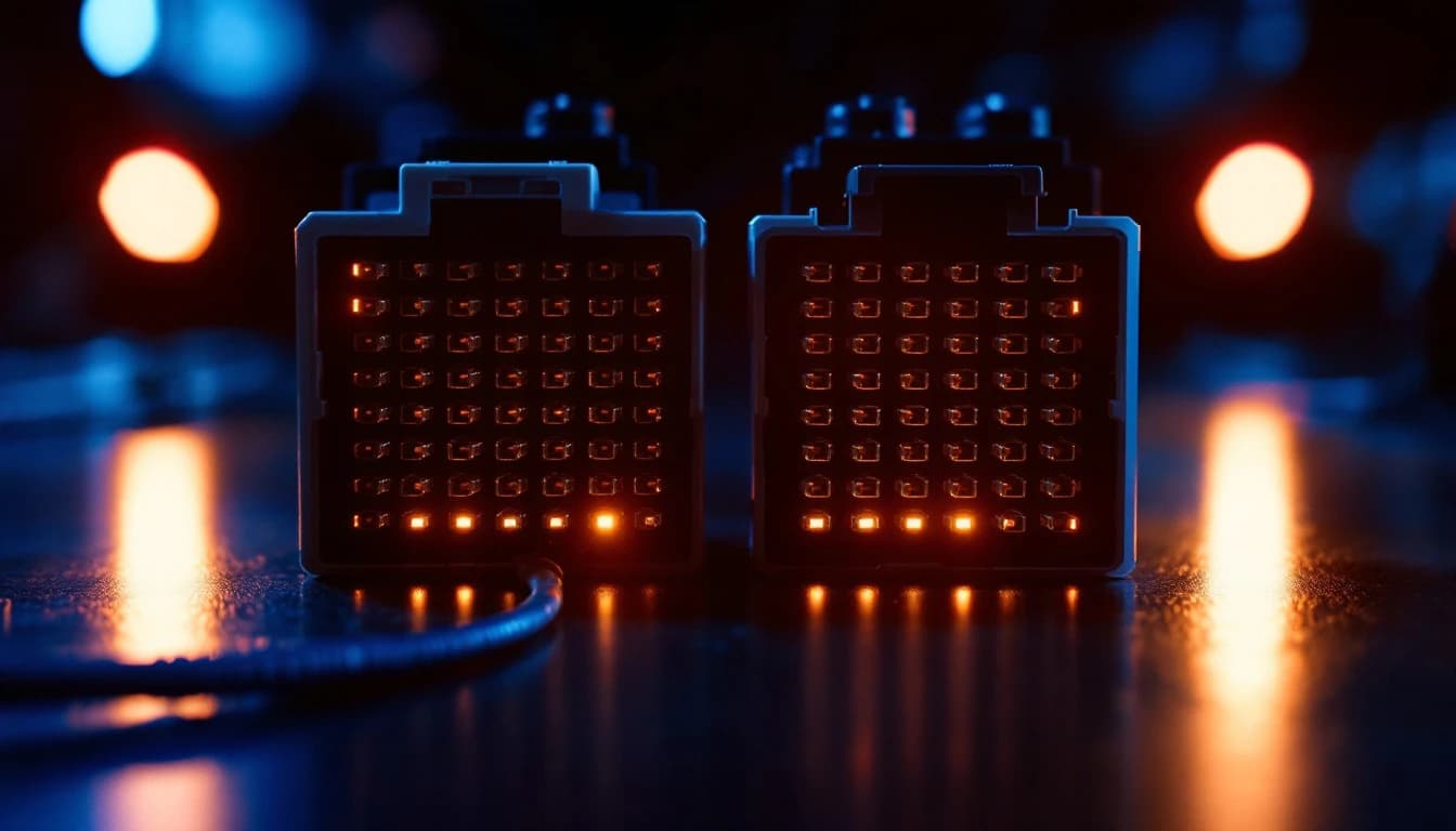
Intake means recording, in order: the outside of the shipping box as received, the module as packed, every face of the housing, the connector cavities, the OEM part number label, any secondary hardware revision markings, and any handwriting a previous shop left on the case. On a module that has been opened before, the state of the potting compound, the conformal coating, and the case screws gets photographed too — because a module that has already been probed by someone else is a different job than a virgin unit, and you want that on record before you own it.
Part numbers matter more than most owners expect. A single vehicle model year can carry several hardware revisions of the same nominal module, and data from one revision is not automatically valid on another. The label usually carries an OEM part number, a supplier part number (Bosch, Continental, Delphi, Denso, Marelli, Siemens/VDO), a hardware index, and often a software or calibration index. On many units the software revision is only readable electronically, after the module boots — which is one more reason the read step comes before the work step.
This matters because the electronics content of vehicles has grown faster than most repair habits have. Bosch, which invented the CAN protocol that most of these modules speak, documents the modern vehicle as a distributed network of dozens of interconnected controllers rather than a handful of standalone boxes — see the technical material published by Bosch Mobility. A well-equipped current vehicle commonly carries well over 100 individual electronic control units on several networks. Industry commentary tracked by outlets like MotorTrend commonly places the software in a current production vehicle at well over 100 million lines of code across those controllers. Every one of those controllers has a part number, a revision, and a compatibility envelope. Guessing is not a strategy.
The consequences show up in ownership data. Vehicle dependability research published by J.D. Power has repeatedly found infotainment and electronics to be the most-reported problem category among owners, accounting for roughly a quarter of all problems reported in recent dependability studies — ahead of the engine and transmission categories that owners traditionally worried about. Electronics are no longer a subsystem of the car. In failure terms, they are the car.
Documentation is also the honest answer to a question customers ask constantly: what happens if my module comes back different than I sent it. The photo set is the answer. It exists so that neither side has to rely on memory.
The bench harness: rebuilding a car on a workbench
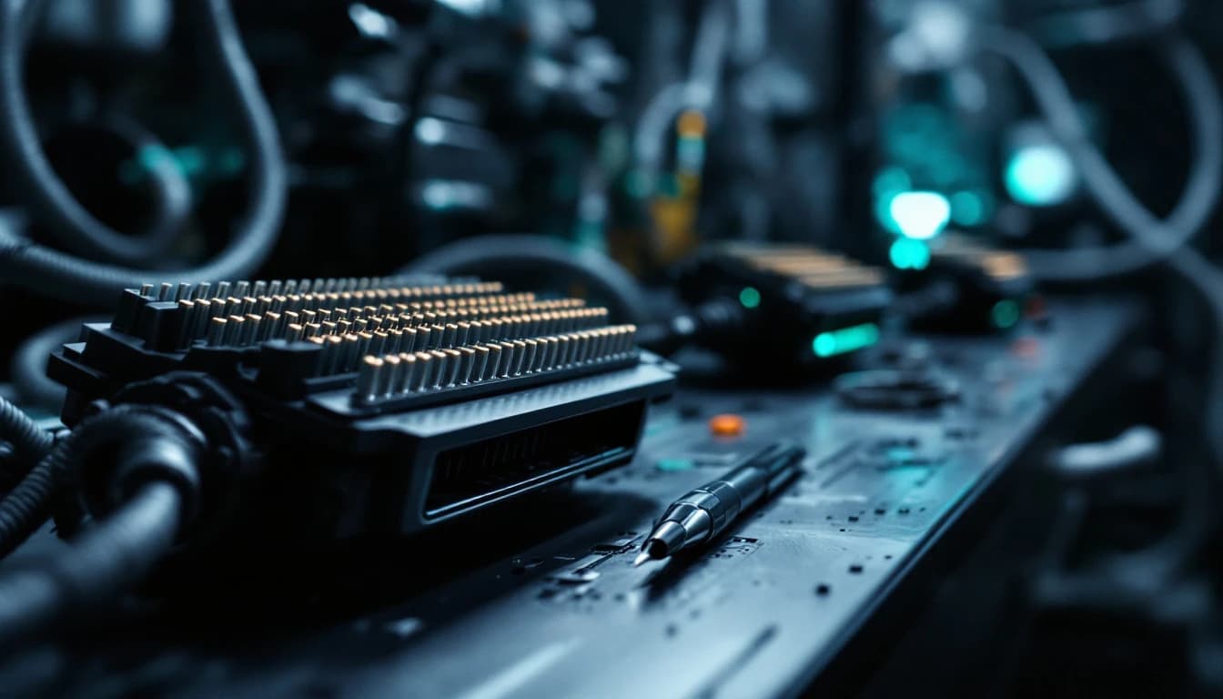
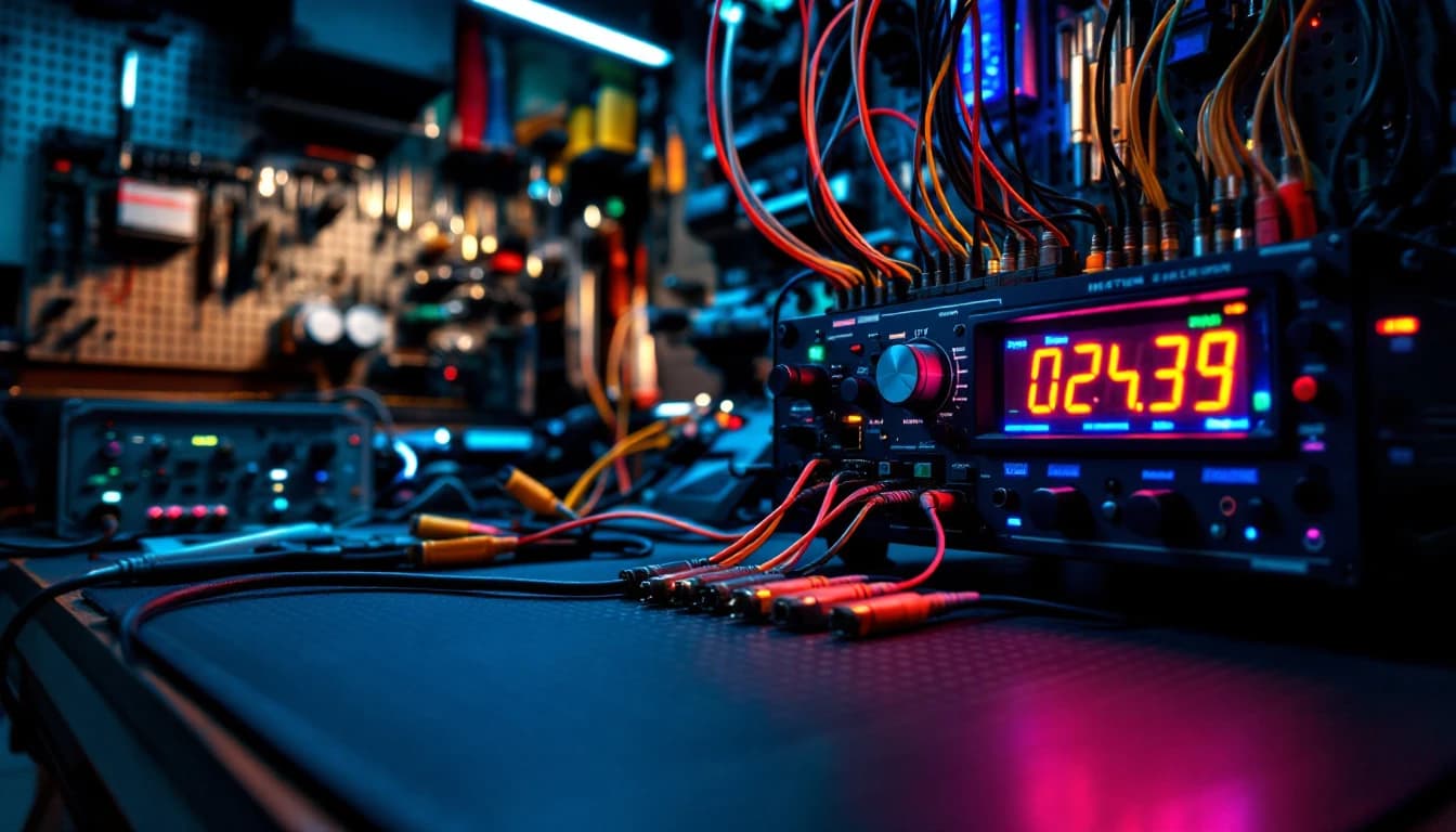
A control module does not know it is out of a car. It only knows what arrives on its pins. A bench harness is a purpose-built loom that presents the module with the minimum electrical environment it needs to boot and communicate:
- Constant battery positive (B+) — the permanent 12-volt feed that keeps memory alive
- Switched or ignition-on power — the signal that tells the module the key is on and it should come out of sleep
- Ground — usually several separate grounds, sometimes split between power ground and signal or logic ground
- CAN-H and CAN-L — the twisted differential pair the module uses to talk to everything else
- Bus termination — typically a resistor at each end of a high-speed CAN segment, because an unterminated bus reflects signals and communication becomes unreliable or impossible
- Whatever else that specific module demands — a K-line for older ISO 9141 or KWP2000 units, a LIN line, a crank or speed input, a wake-up line, an immobilizer link, sometimes a specific resistance or a load the module checks for before it will play along
That last bullet is where bench work stops being generic. Some modules boot happily on four wires. Others refuse to leave a protected state unless they see a plausible vehicle around them. An instrument cluster may want an ignition signal and a bus partner before it lights. A body control module may need a wake-up input. A transmission controller may want to see a sensible sensor reference before it will accept a session.
CAN itself is not a mystery — it is a published standard. The physical and data-link layers are specified in the ISO 11898 family maintained by the International Organization for Standardization, with high-speed CAN specified up to 1 Mbit/s on a properly terminated two-wire bus, and diagnostic transport over CAN standardized in ISO 15765. Diagnostic services and reprogramming access for aftermarket tools ride on standards maintained by SAE International, including the J2534 pass-through specification that lets non-dealer equipment reflash controllers. That pass-through path is not an aftermarket courtesy — U.S. service-information and reprogramming requirements administered by the Environmental Protection Agency obligate manufacturers to make emissions-related reprogramming available to independent repairers through a standardized interface, which is a large part of why bench-side reprogramming is a legitimate trade at all. The lab's harness is simply an honest, minimal implementation of what those documents say the module is entitled to expect.
Pinouts: the part that separates a lab from a guess
A harness is worthless without the correct pinout — the map of which physical cavity in the module's connector carries which function.
Finding it is deliberate work. The sources a technician uses, roughly in order of trust:
- OEM service information and wiring diagrams for the exact model year and engine or body variant. This is the primary source, and it is specific: the same connector shell can be wired differently across variants.
- Connector views that show cavity numbering as seen from the terminal side versus the mating side. Reading a connector diagram from the wrong side is one of the most common ways an experienced person still gets it wrong.
- The module's own supplier documentation, where available, which sometimes numbers pins differently from the vehicle diagram.
- Continuity and resistance measurement on the module itself — confirming that a suspected ground pin actually reads near zero ohms to the housing or to the other grounds, and that a suspected CAN pair reads the characteristic resistance you would expect between CAN-H and CAN-L.
- Voltage-free verification before energizing — checking that nothing is shorted, that the supply pins are not tied to ground internally, and that the harness itself is built correctly, unpowered, with a meter.
Only after that does anything get switched on, and the first power-up is done with the bench supply's current limit set low. A module drawing a sensible quiescent current is a module that is probably wired correctly. A module that immediately pulls the supply into current limit is telling you to stop.
What happens when a pinout is wrong
Be blunt about this, because it is the reason the verification steps above exist.
- Reversed polarity on the main feed can destroy the module's input protection, its regulator, or more, in well under a second. Some units survive on a protection diode. Many do not.
- Battery voltage applied to a signal or communication pin can take out the transceiver, the microcontroller port, or both. The module may still power up and simply never communicate again.
- A missing or wrong ground produces the most confusing failures: the module half-boots, behaves erratically, communicates intermittently, or resets during a write. Current then looks for a return path through whatever else is connected — which is precisely how a bad ground damages a communication line.
- CAN-H and CAN-L swapped usually produces no communication at all rather than damage, which is the merciful outcome.
- No bus termination gives you an intermittent connection that appears to work until exactly the moment you least want it to — mid-write.
A module that is bricked by a wiring mistake is not always recoverable, and a lab that pretends otherwise is not being straight with you. This is why the sequence is documentation, verification, low current limit, and only then power. Where a module arrives in an unknown or already-damaged state and nobody can promise an outcome up front, the honest product is a paid diagnostic rather than a promise — that is exactly what a bench evaluation and custom job at $150 exists for, with the module photographed on the bench and a real quote issued before any repair proceeds.
"The number of modules I get sent that were already killed by somebody's homemade bench setup is not small. Nine times out of ten it is a ground problem or a diagram read from the wrong side of the connector. Take the extra ten minutes, ring out the harness cold, and start with the supply current-limited. The ten minutes is always cheaper than the module." — Independent automotive electronics technician, 20+ years in module-level bench repair (anonymized)
Bench power: why a regulated supply is not optional
Everything above assumes clean power. This is the single most underrated part of the bench.
Automotive electronics are designed to survive a hostile electrical environment — the general environmental and electrical stress conditions for vehicle electronics are described in reliability practices published by SAE International — but "survive" and "reliably accept a flash write" are different requirements. Software integrity in these controllers is taken seriously at the regulatory level too: recall campaign records published by the National Highway Traffic Safety Administration cover tens of millions of vehicles in a typical year, and software and control-module remedies now make up a substantial and growing share of those campaigns rather than a rounding error. During reprogramming, a module erases and rewrites flash memory. If the supply sags below the module's operating threshold in the middle of that operation, the write is incomplete and the module can be left without a valid bootable image. That is the textbook definition of a bricked module, and it is why manufacturers insist on a battery maintainer during in-vehicle reprogramming.
A bench supply removes the variable entirely:
- Regulated, adjustable output, held at a specified voltage rather than whatever the car's battery happens to be doing
- Adjustable current limit, so a wiring mistake trips a limit instead of cooking a board
- Live current display, which is genuinely diagnostic — quiescent draw, wake-up draw, and an abnormal draw all look different
- No alternator ripple, no starter draw, no accessory load, no corroded chassis ground in the path
That last point deserves emphasis. In a vehicle, a flash attempt is at the mercy of the car's charging system and grounds. Chronic electrical faults — a weak battery, a failing alternator, corroded ground straps — cause brownout resets and corrupted writes, which is a whole failure family in its own right. If you are chasing a module that keeps failing after replacement, read the companion piece on why a replacement module fails too after this one; a bench can restore a module, but it cannot fix a car's charging system remotely.
Reading first: the backup dump is not optional either
Before any change, the module gets read.
A full read means capturing what is actually in the device — flash and EEPROM where accessible, along with the identifiers the module reports: VIN, part numbers, hardware and software versions, coding and configuration data, and any security or immobilizer-related content the job requires. That capture is archived before a single byte is modified.
There are three reasons this is non-negotiable:
Recovery. If anything goes sideways during the write, the original image is the way back. Without it, there may be no way back at all.
Comparison. Verification later depends on knowing exactly what was there before. Diffing a post-write readback against a pre-work dump is how you prove that only what was supposed to change actually changed.
Honesty. The dump frequently reveals that the module is not the problem, or that the module has already been modified by someone else, or that a prior attempt left it in a partially written state. It is far better to discover that before touching it than to discover it after.
Some jobs are entirely read-and-write jobs by nature. Cloning is the clearest example: a GM BCM standalone clone at $199 transfers VIN, mileage, theft-system, and option coding from an original body control module onto a matching donor, and the entire value of the service is that the read is complete and faithful. Unlocking is another: a Chrysler GPEC PCM unlocking service at $250 removes the factory security restriction that prevents tuning software from reading or writing the calibration at all — and the archived original is what makes a later restore possible.
The programming step
By the time anything is written, the interesting decisions have already been made. The write itself should be boring.
What that step actually consists of depends on the job: writing a modified calibration back, transferring an identity from an original to a donor, writing corrected coding or configuration, clearing stored crash or fault data on a module type where that is the defined repair, resetting a security state, or restoring an image after a component-level board repair. Different module families use different access paths — a standardized diagnostic session over CAN, a supplier-specific boot mode, or direct access to the memory device on the board where the microcontroller will not cooperate.
Two constants apply regardless:
- The supply stays regulated and monitored for the entire operation. Nothing else gets plugged in, unplugged, or moved.
- The operation is not declared successful because the software said so. Software reports success on a write that later fails to boot more often than anyone would like. Success is what verification demonstrates, not what a progress bar claimed.
Verification: readback, checksum, functional test
Verification has three layers, and skipping any one of them is how a shop ends up shipping a module that fails in the customer's driveway.
Layer one — readback. After the write, the module is read again and the retrieved image is compared to what was intended to be written, byte for byte where the memory map allows. A mismatch here is caught on the bench, where it is a nuisance, instead of in a vehicle, where it is a tow.
Layer two — checksums. Most calibration and configuration areas carry checksums or integrity values that the module itself validates. A written image whose checksum does not compute correctly may load and then be rejected, or may cause the module to fault in ways that look like a completely unrelated problem. Checksum correctness is confirmed as part of the write, and again on the readback.
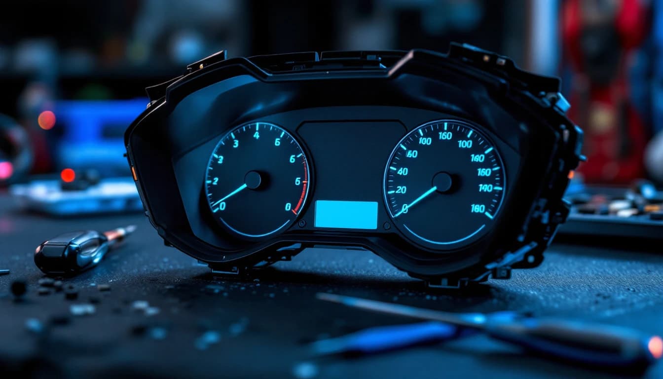
Layer three — functional bench test. The module is power-cycled and brought back up from cold on the harness. Does it boot? Does it respond to a diagnostic session? Does it report the identifiers it should report — the right VIN, the right part numbers, the right software version? Do the outputs a bench can exercise actually respond? For a cluster, do the gauges sweep and does the display show what it should? For a body module, do the driver outputs switch?
None of this proves the vehicle's own problem is solved — a bench cannot test a module against a car it is no longer connected to, and any honest lab says so plainly. What verification proves is that the module leaves the bench booting, communicating, and carrying the data it is supposed to carry. What that guarantee does and does not cover is worth reading in full in what to expect from a mail-in programming warranty.
Why the bench beats the car for dead, locked, and no-comms modules
Here is the direct comparison, because this is the question underneath most of the emails a lab receives.
| Situation | In the vehicle | On the bench |
|---|---|---|
| Module will not communicate at all | Dead end — no session, no access, no diagnosis | Direct connection to the module's own pins; boot mode and board-level access available |
| Module is security-locked from the factory | Blocked at the gateway; tool is refused | Access at the module, outside the vehicle's security context |
| Supply voltage during a write | Depends on the car's battery, alternator, and grounds | Regulated, current-limited, monitored throughout |
| Recovering from a failed or interrupted flash | Often impossible in-car | Backup image plus boot-mode or direct memory access |
| Cloning identity to a donor module | Not a vehicle-side operation | Both units on the bench, read and write side by side |
| Component-level board repair | Not possible with the module installed | Board accessible, testable, and re-verifiable after repair |
| Diagnosing whether the module is even the fault | Confounded by wiring, grounds, and other modules | Module isolated — its behavior is its own |
The pattern is consistent. Anything that depends on the vehicle cooperating — a live gateway, a healthy bus, a good battery, an unlocked module — is a job the car can sometimes do. Everything that begins with the module already refusing to cooperate is a job that only a bench can reach. That is the entire reason mail-in bench work exists as a category, and it is why a dealer's honest answer is sometimes that they cannot help; there is a separate walkthrough of that scenario in what to do when the dealer says they cannot program your module.
Packing and shipping back
The last technical step is physical. A module that survived every electrical hazard in the lab can still be destroyed by a courier.
Return packing means an anti-static bag around the module, connector cavities protected, the unit immobilized inside the inner box so it cannot move, and enough surrounding cushion that a drop on any face does not transmit to the board. Loose modules rattling in an oversized carton crack solder joints and bend connector pins, and neither failure is obvious on arrival.
Return shipping is paid by the customer and chosen at checkout, starting from $29.95, with faster tiers available when a vehicle is down and days matter. Tracking goes out with the shipment. Inbound, the ship-to depends on carrier: USPS goes to PO Box 120241, Arlington, TX 76012, while UPS and FedEx must go to 1009 Oakwood Ln # 120241, Arlington, TX 76012, because couriers cannot deliver to a USPS PO Box. All bench work is performed at the Arlington workshop; Auto Module Lab is mail-in only and does not offer on-site or mobile service.
For key, immobilizer, and other security-related work, proof of ownership is required before anything is programmed. That is not a formality — it is the line between legitimate repair work and something else.
Frequently asked questions
What exactly is a bench harness? A bench harness is a purpose-built wiring loom that supplies a control module with the minimum electrical environment it needs to boot outside a vehicle: constant battery power, switched or ignition power, ground, and a properly terminated CAN-H and CAN-L pair, plus any module-specific inputs such as a K-line, a LIN line, or a wake-up signal. It lets a technician power, read, write, and test the module on a workbench with no car attached.
How does a technician know which pin is which? From OEM service information and connector diagrams for that exact model year and variant, cross-checked against supplier documentation where available, then physically confirmed on the module with a meter before power is applied. Ground pins are verified for near-zero resistance to the other grounds, and the CAN pair is verified by its characteristic resistance. Connector diagrams are read carefully for terminal-side versus mating-side numbering, which is the classic way an experienced person still gets it wrong.
What happens if the pinout is wrong? Reversed polarity on the main feed can destroy the module's protection and regulator circuitry in under a second, and battery voltage on a communication or signal pin can take out the transceiver or the microcontroller port permanently. A wrong or missing ground is the sneakiest failure, producing half-boots, intermittent communication, and resets during a write. That is why the harness is rung out cold with a meter first and the first power-up is done with the supply current-limited.
Why does a regulated bench power supply matter so much? Because a flash write erases and rewrites memory, and a voltage sag partway through leaves the module without a valid image — the textbook way a module gets bricked. A regulated supply holds voltage steady, limits current so a wiring error trips a limit instead of cooking a board, and removes alternator ripple, starter draw, and corroded chassis grounds from the equation entirely.
Do you always take a backup before making changes? Yes. A full read of the accessible flash and EEPROM plus the module's reported identifiers is archived before any byte is modified. It exists for recovery if a write fails, for byte-level comparison during verification, and because a pre-work dump frequently reveals that the module was already modified by a previous attempt.
How do you verify the work before shipping it back? Three layers: a post-write readback compared against what was intended to be written, confirmation that checksums and integrity values compute correctly, and a cold functional bench test where the module is power-cycled, brought back up on the harness, and checked for boot, diagnostic response, correct reported identifiers, and working outputs. A module does not ship on a software success message alone.
Can bench work prove my car's problem is fixed? No, and any lab that claims otherwise is overselling. A bench proves the module boots, communicates, and carries the correct data. It cannot test the module against a vehicle it is no longer connected to, and it cannot fix wiring, grounds, charging-system faults, or mechanical problems in the car. If a correctly programmed module still misbehaves after installation, the fault is almost always elsewhere in the vehicle.
The bottom line
A module repair lab is not a laptop and a hunch. It is a controlled environment built to remove every variable a vehicle introduces: a harness that gives the module exactly the power, ground, ignition, and terminated bus it expects; a pinout confirmed from service data and then physically verified with a meter before anything is energized; a regulated, current-limited supply that cannot sag mid-write; a full backup dump archived before the first byte changes; and a three-layer verification pass — readback, checksum, cold functional test — before the unit is packed.
The discipline exists because the failure modes are unforgiving. A reversed feed, a floating ground, an unterminated bus, or a voltage sag during a flash can turn a repairable module into scrap in a moment. Documentation, meter-first verification, and archived backups are what stand between a routine job and an unrecoverable one.
That control is also why the bench wins outright on the hard cases: modules that will not communicate, modules locked from the factory, modules left half-written by a failed flash, cloning an identity onto a donor, and board-level repair. Those jobs are not slower in a vehicle — they are unreachable there.
If you have a module that fits a defined service, start on the services hub. If it does not fit one — or if nobody can tell you yet what is actually wrong with it — a bench evaluation is the honest starting point: diagnosed on the bench, photographed, and quoted before any repair begins. Text us the part number and a photo of the label and we will tell you what we can and cannot do before you ship anything.
Ship your module today
Flat-rate pricing, typical 24-hour bench turnaround, return speed your choice at checkout. Most jobs back on your bench within a week.